
Introduction

The Ultimate 64 RGB LED Controller is an addon module for the Ultimate 64 (U64), which allows you to select your own custom LED colours for the power & activity LED. The colours can be change by using a simple basic tool which communicates over the serial port (userport) with the module.
Download project files
!WARNING!
An issue has been reported on Ultimate 64 version >=1.3 boards, the machine didn’t boot when the addon is installed.
I’m looking for an answer/solution why it won’t boot.
Update: 22-12-2020
!WARNING!
https://github.com/iamtsb/u64_rgb_led_controller
Connectors

The module has the following connectors:
- J1: Userport socket
- Connects module to Ultimate64 userport
-
J2: Userport passthrough
-
J5: LED Strip connector, see pinout below
-
J3: RGB LED connector, for RGB Led with common cathode (see pinout below)
-
J4: Activity connector that must be connected to the LED header on the U64
-
J6/J7/J8: jumpers to enable or disable the serial communication between the U64 and the module so you can use other serial devices
- J6: Connect TxD (PA2) to Arduino MCU
- J7: Connect RxD (PB0) to Arduino MCU
- J8: Connect PB0 & /FLAG2 signals, that’s needed in order to receive data on the serial port (userport)
Pinouts
RGB LED

LED Strip

USRCTL0 = LED Clock (C0 or CLK1 on LED strip)
USRCTL1 = LED Data (D0 or SD1 on LED strip)
More information: https://1541u-documentation.readthedocs.io/en/latest/hardware/ledstrip.html
Activity header

Module installation


First connect the LED Strip cable connector to J5 (LED Strip header)


Connect the LED cable connector to J3 (LED header), and connect the module to the U64 Board.


The last step is to connect the cable from J4 (ACT LED) to the LED connector of the U64 Board.

Only the 1st and 3th wire must be populated of the header socket.


BEFORE POWERING UP THE MACHINE CHECK IF THE BOARD SOCKET IS IN LINE WITH THE USERPORT HEADER!!
Software
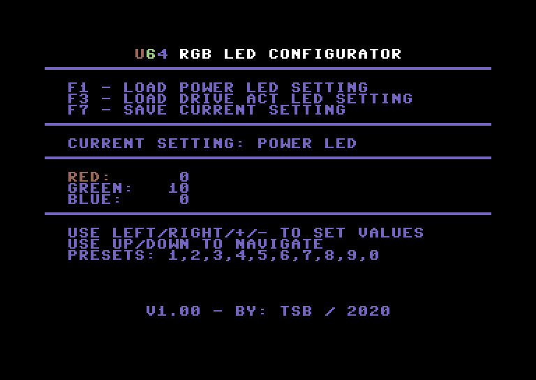
The C64 tool allows you to mix the RGB colours into a flavor you like.
To make the programming possible add jumpers to J6, J7 & J8.
Keys:
F1: Load power LED setting
F3: Load activity LED setting
F7: Save current setting to eeprom
Use Left & Right arrows to change value with 1 step, + & – with 5.
0..9 are preset colours.
If the power and activity LED is not corresponding with the setting you made just place the connector on the LED header of the U64 board the other way around.
Software can be downloaded from the github repository.
Hardware design / build
CHECK CHECK CHECK
When soldering a solder blob/bridge can be created accidentally, so check all solder joints!
After the build (double) check for shorts between pins on the Arduino and the other connectors.
Also check if there is no short between 5V & GND.
IF YOU DON’T HAVE SKILLS TO SOLDER, PLEASE ASK SOMEONE ELSE TO BUILD THE BOARD WHO HAVE THOSE SKILLS
Schematics

Board design
Prototyping the project:

Board designs:


To make the programming possible add jumpers to J6, J7 & J8.
Gerber files can be downloaded from the github repository.
Used components (bill of material)
| Code | Part |
| – | U64 RGB LED Controller PCB |
| U1 | Arduino Nano V3 |
| J1 | 2×13 row 2,54mm pitch, socket |
| J2 | 2×13 row 2,54mm pitch, pin header |
| J3, J4 | header: 4 pin angled 4 pin header (2,54mm pitch) |
| J6, J7, J8 | header: 2 pin straight (2,54mm pitch) |
| – | 3x jumper 2,54mm |
| – | wire for 2 pins |
| – | Jumper cable, 3 pin, for led connector U64 board |
Flashing code into the Arduino nano v3

Before you can upload the code to the MCU you must download the Arduino IDE.
Download: https://www.arduino.cc/en/software
After installation the IDE connect the Arduino Nano v3 to a USB port and wait until the driver installation is finished.
Arduino IDE board / serial port settings
You have to select the right board & port.
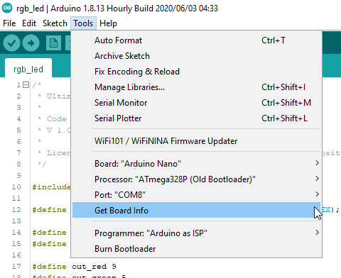
Board: Arduino Nano
Processor: ATmega328P (Old Bootloader in my case)
Port: COM8 (in my case)
Upload sketch to board

If everything went right, you see something like this:

Now you can connect the module to the Ultimate 64 board. See module installation.
Disclaimer
The project described on this page is a hobby project, I took all the effort to describe all the information on this page as completely and as carefully as possible.
I can not be held responsible for any damage to your equipment, building this project is entirely at your own risk. If you do not have the knowledge to build this project, ask someone who does have this knowledge to prevent damage to your devices.
Use at your own risk.
I stumbled across your LED Controller Board on my search to find a way to control a LED Strip on a U64, and set the Colours with a C64 Program.
Looks like J5 on the Board is not connected to the Arduino, only the Power / Drive LED.
Is there a chance for a new Revision with J5 attached to the Arduino, so that the LED Strip is accessible in a way you did it the the Power LED ?
By now, a LED Strip is only useful for SID Disco, which is quite a shame 😉
Hope to hear from you.
Greets, Larry
J5 is only a passthrough, the led strip can not be controlled by the arduino board.
It only controls the power/drive led.