
Pioneer CLD-515 Power Supply Fix

Some WARNINGS before you start to fix your own PSU:
- If you have no experiences with repairs like this DON’T DO IT!
- If you try to fix it, it is at your own risk!
- Beware of the HIGH 300V+ (DC) voltages!!
- Beware that some capacitors can hold high voltages for some while, unload them with a resistor!
- Use a current limiter that protects against short circuit. It’s a lamp which is in series with a outlet (see the one I use in the picture above, it’s on the right side).
- Ensure the power is turned off before touching the board!
Let’s start..
On the bench a Pioneer CLD-515 Power Supply, which is not working. All output voltages are 0V.
First check:

Check DC voltage after the Bridge Rectifier D1, this must be around 310V DC. In my first meassurement it is 320V DC. That is a bit high but D1 is working.

Then if we look futher into the schematic, I checked the values of R3,R4,R5,R6, those are looking good.

Now I am going to check C12, this capacitor starts (pulse) the mosfet.


I desoldered the capacitor, it must have a value of 1uF.

I meassured it with my LCR meter, if you look to the value quickly you see a value of 910, first I thought a 910nF that’s good.. but if you look a bit closer you see 910 pF which is not even 1nF and 1000 times smaller than 1uF.. the ESR value is 0R, that not good at all!!
So.. the mosfet start capacitor is death.. I have to order it because I didn’t had a 1uF/400V cap.

The new one, 953 nF with a esr of 11,54.. that’s ok!

Meanwhile I also checked the C11 (100uF/400V) capacitor. It meassured 80uF so that is also a candidate to be replaced.


New capacitors are in place, so let’s test it.

All voltages are back and fine now!
So the problem was the start capacitor C12.
Resources
Download the schematic: Pioneer CLD D515 Schematic
Capacitor unload cable I use:
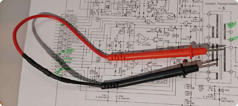
2 probes with 2 * 470 Ohm in series between the probes. With this I can unload the capacitor before touching it. Thanks to my friend Gert who brought it to my attention!