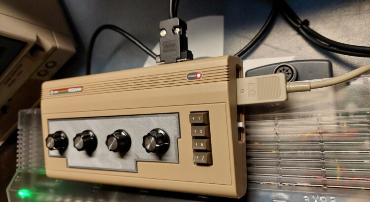
While I was looking for a nice case to house the MSSIAH controller, I came across a broken THE C64 mini I got a while ago. Wouldn’t it be awesome to use this for the housing? YEAH!
Ingredient list
- (Defective) THE C64 mini
- 4x Linear Potentiometer 220KΩ
- 4x Trim potentiometer 250KΩ
- 4x Resistor 8k2 Ω
- 4x Capacitor 4700pF
- 2x joystick extension cables
- 1x 15pin D-Sub Female connector
- 1x 15pin D-Sub Male connector
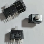
- 1x 8.5mm x 13mm, 12 pin switch
- Some wire
- 3D printer to print some custom parts for replacing parts of the THE 64 mini.

Start with a schematic
I wanted to design a own schematic, but while investigating the working of the MSSIAH controller options and paddle options of the C64, I came across a schematic by InactiveX.
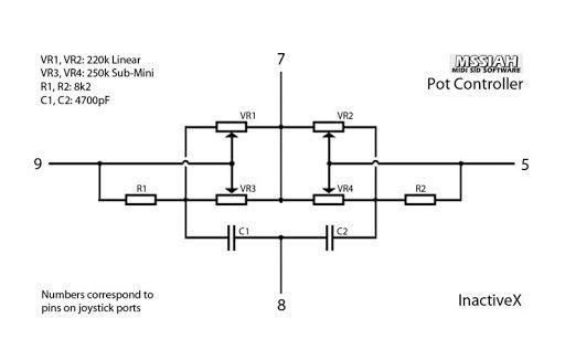
So there is no need to design / figure out a design by myself, I took this schematic and remade it in kicad.
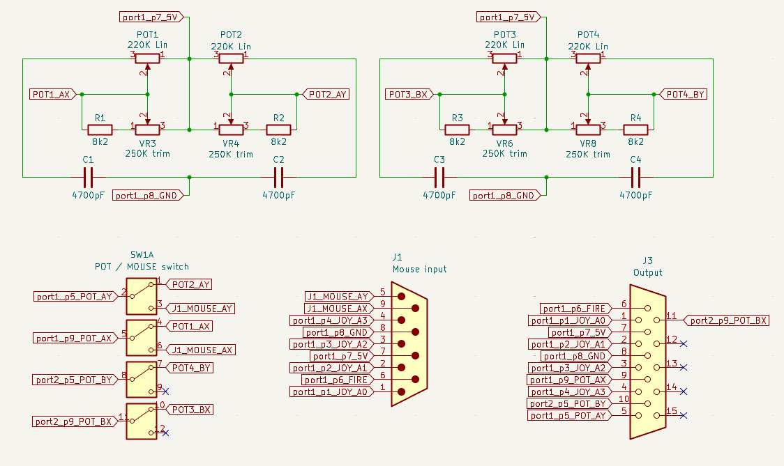
The output of the POTS (POT1..POT4) are going to the switch (SW1), and from there it goes to the output connector (J3). On the Switch (SW1) is also the mouse input (j1), so there can be switched between mouse and POTS. All the (extra) pins of the Port 1 is also going to the mouse input (J1)
The 3D parts

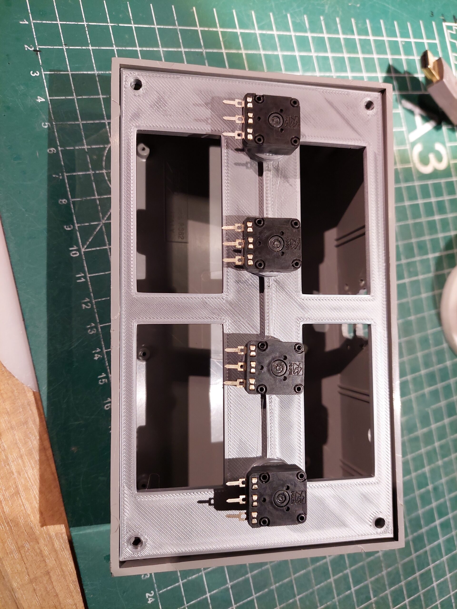
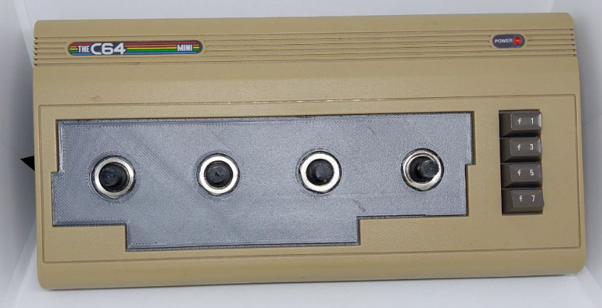
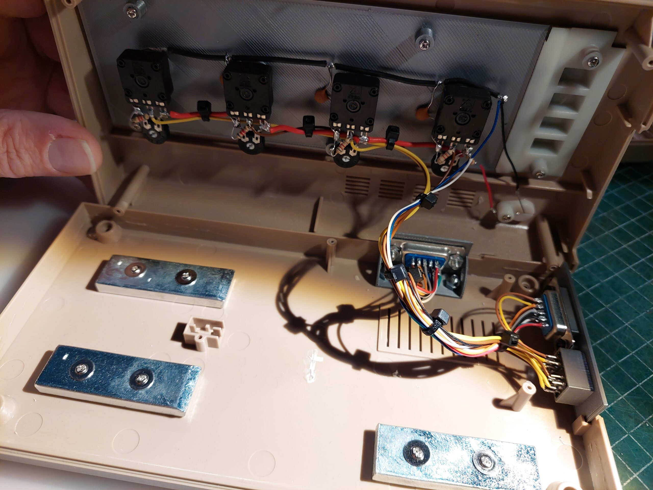
I replaced the “keyboard” part of the original THE C64 with a new plate that can hold the potentiometers.

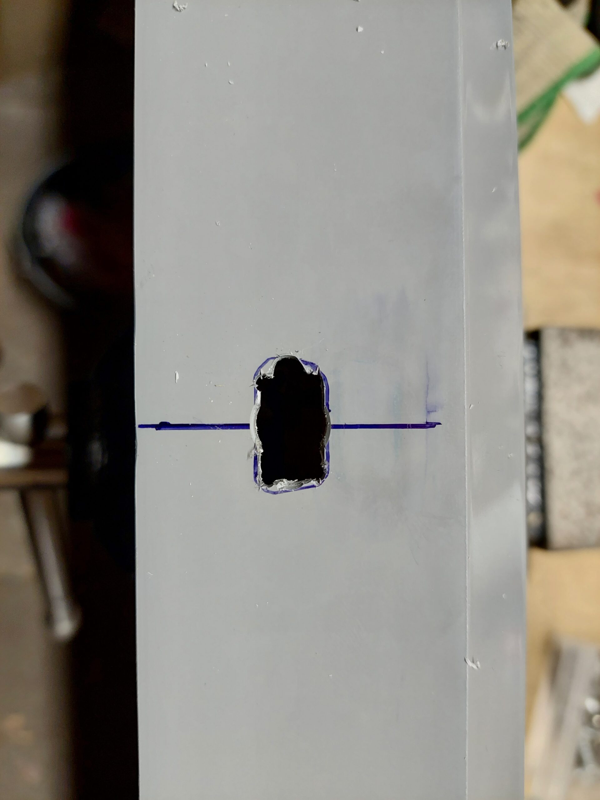
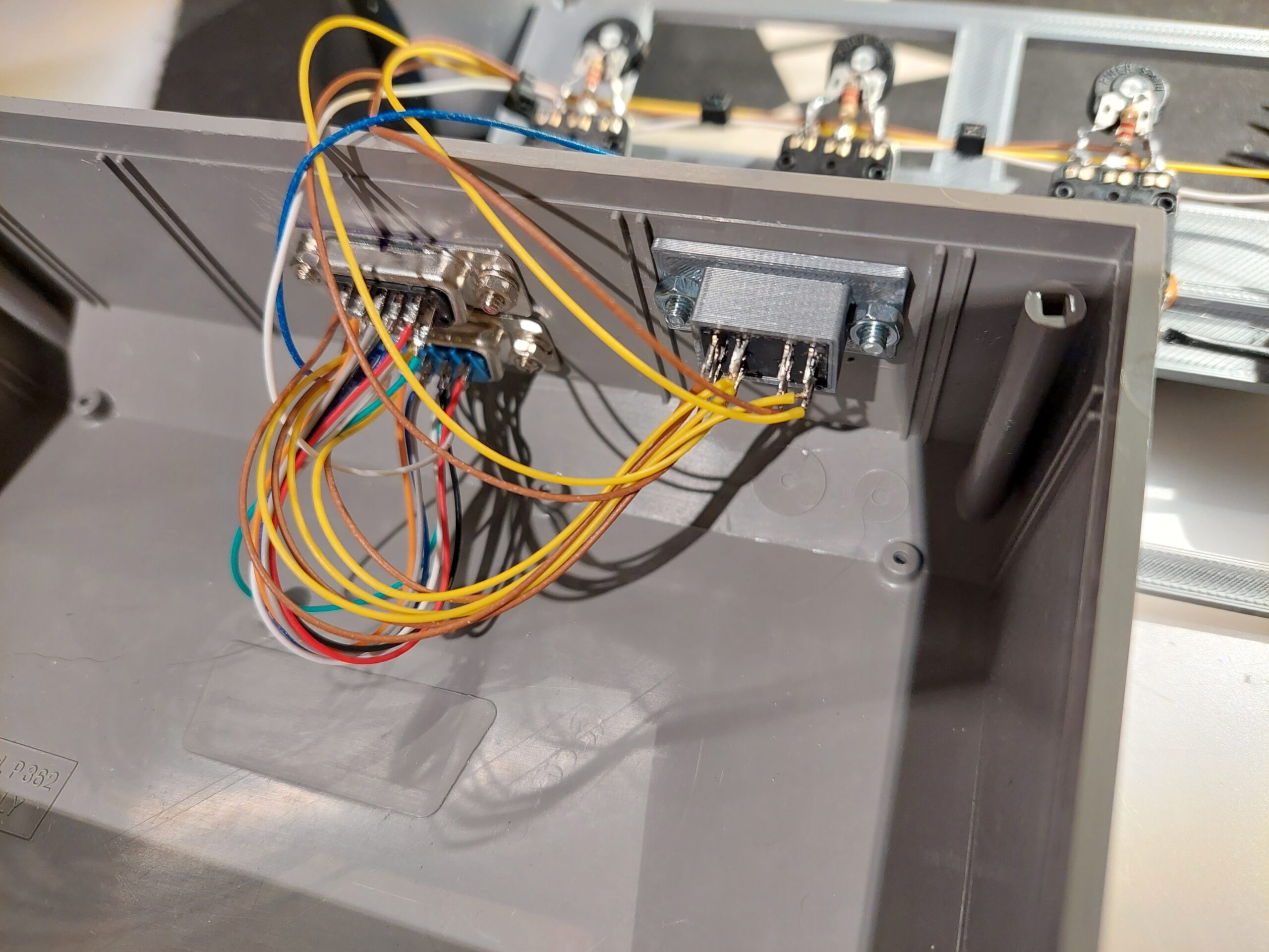
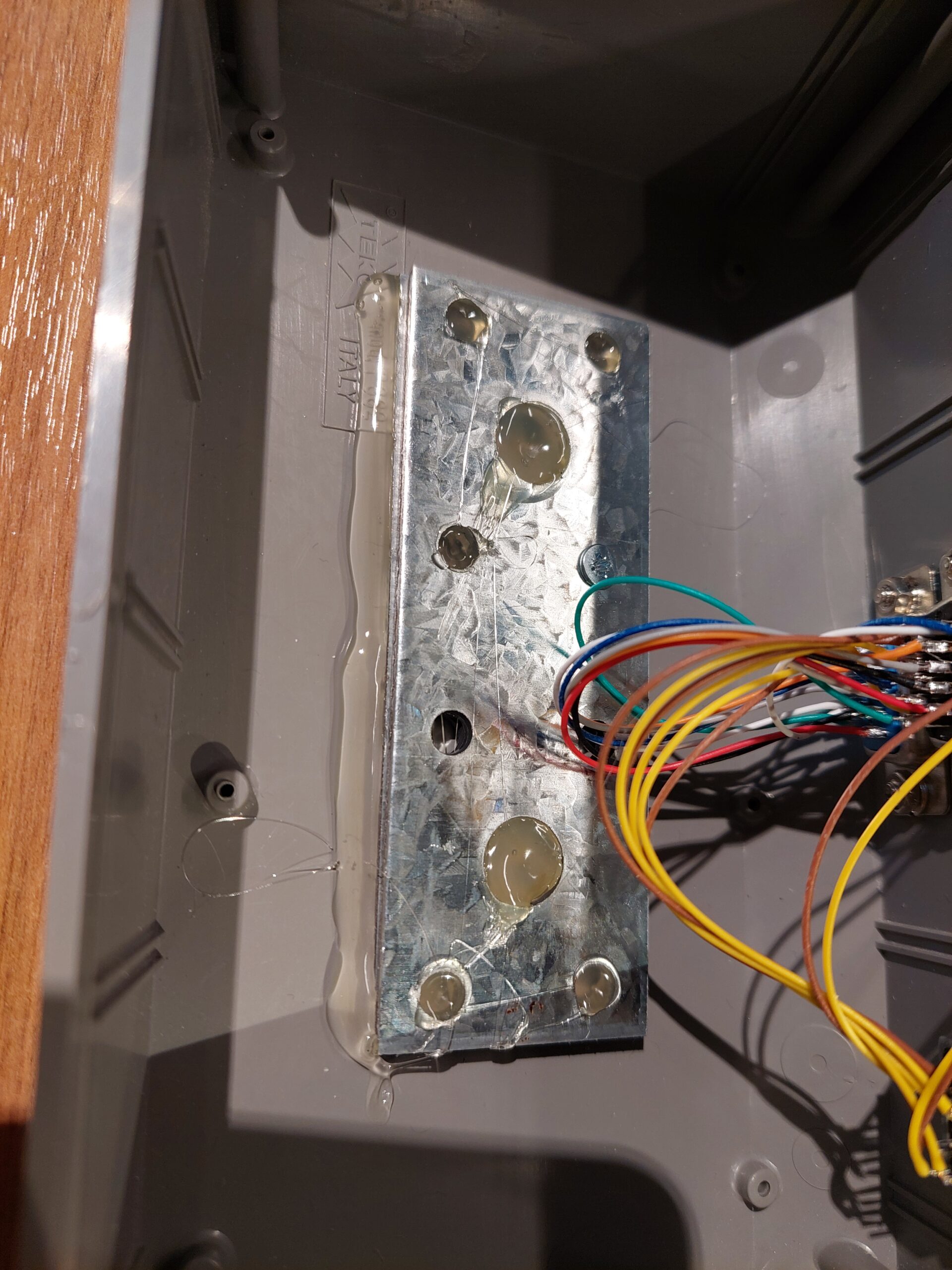
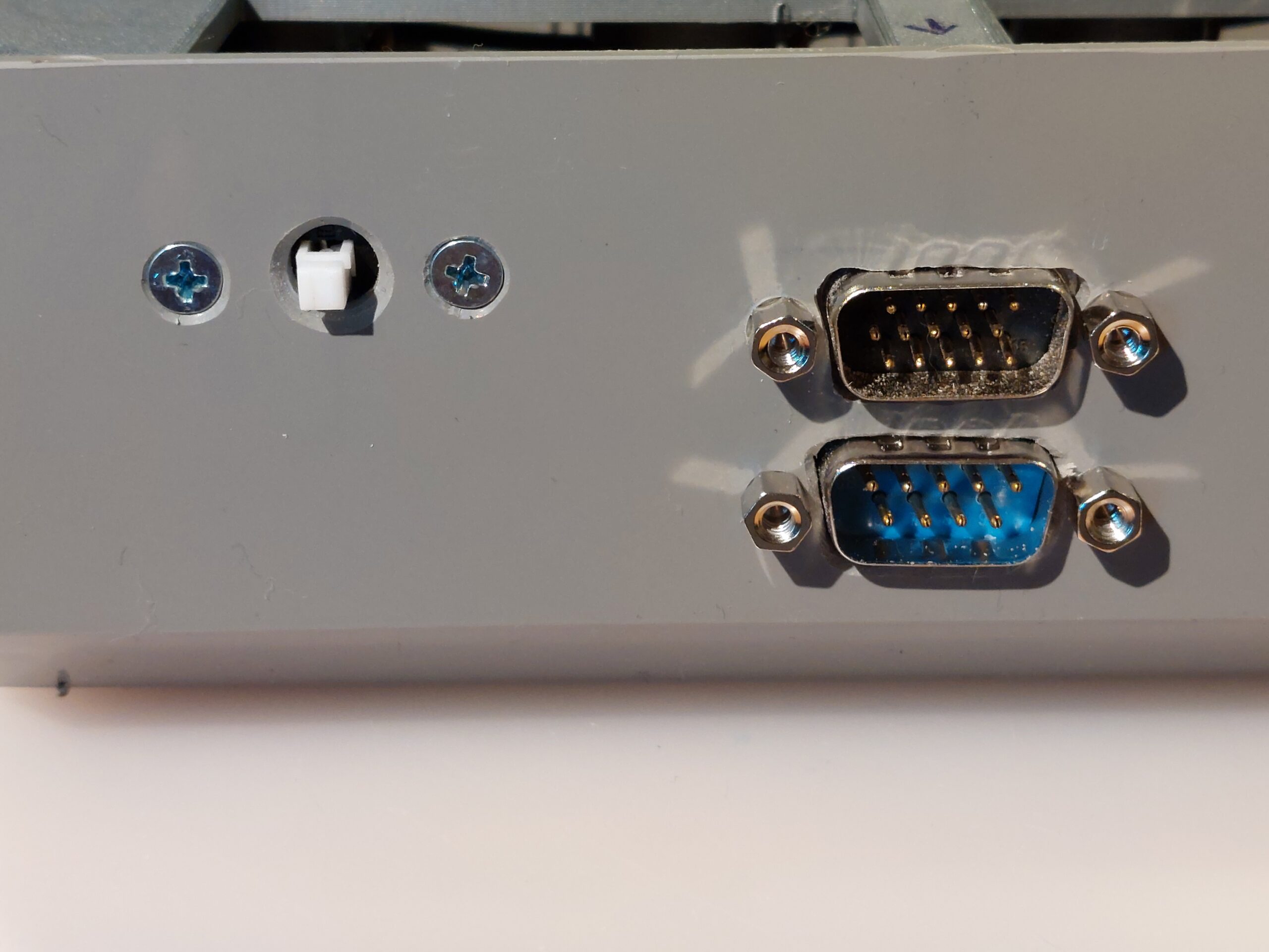
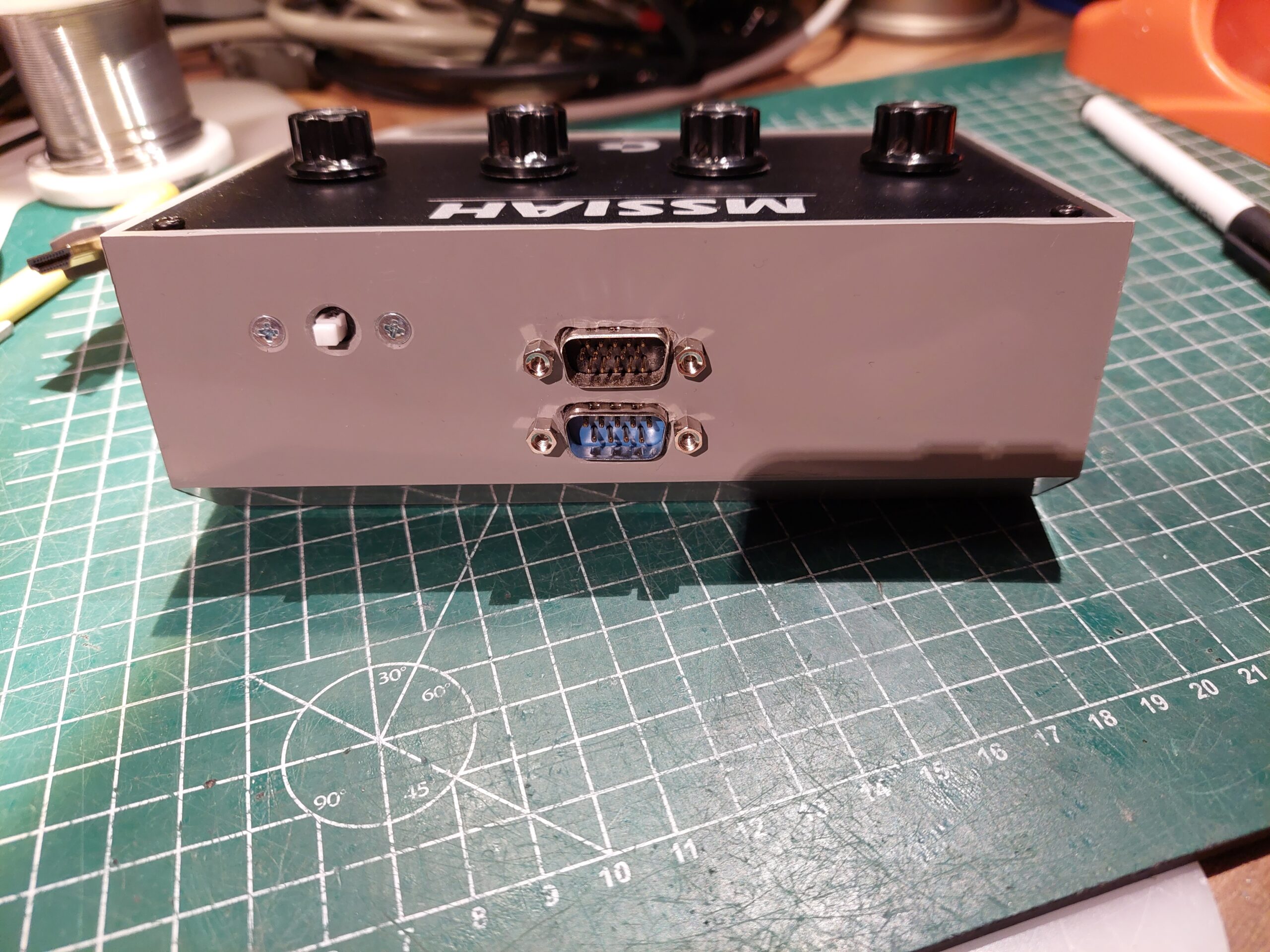
The side plate which normally holds the USB and power button of THE C64 is replaced with a plate which can hold a D-Sub 9pin male connector for connection the mouse and a switch to switch between mouse and potentiometers.

And for the back a mounting for the output which will be connected to the C64


Some pictures
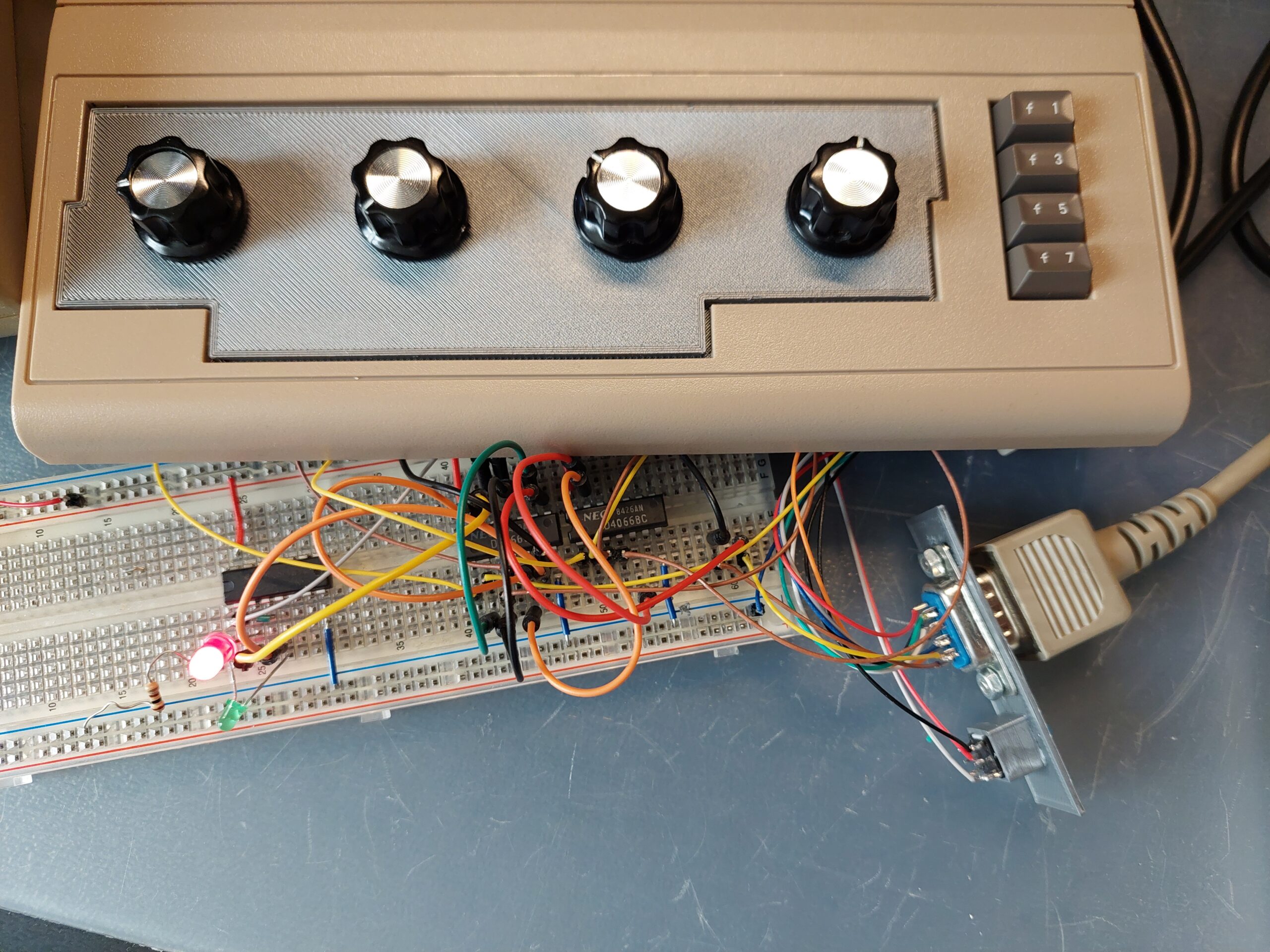
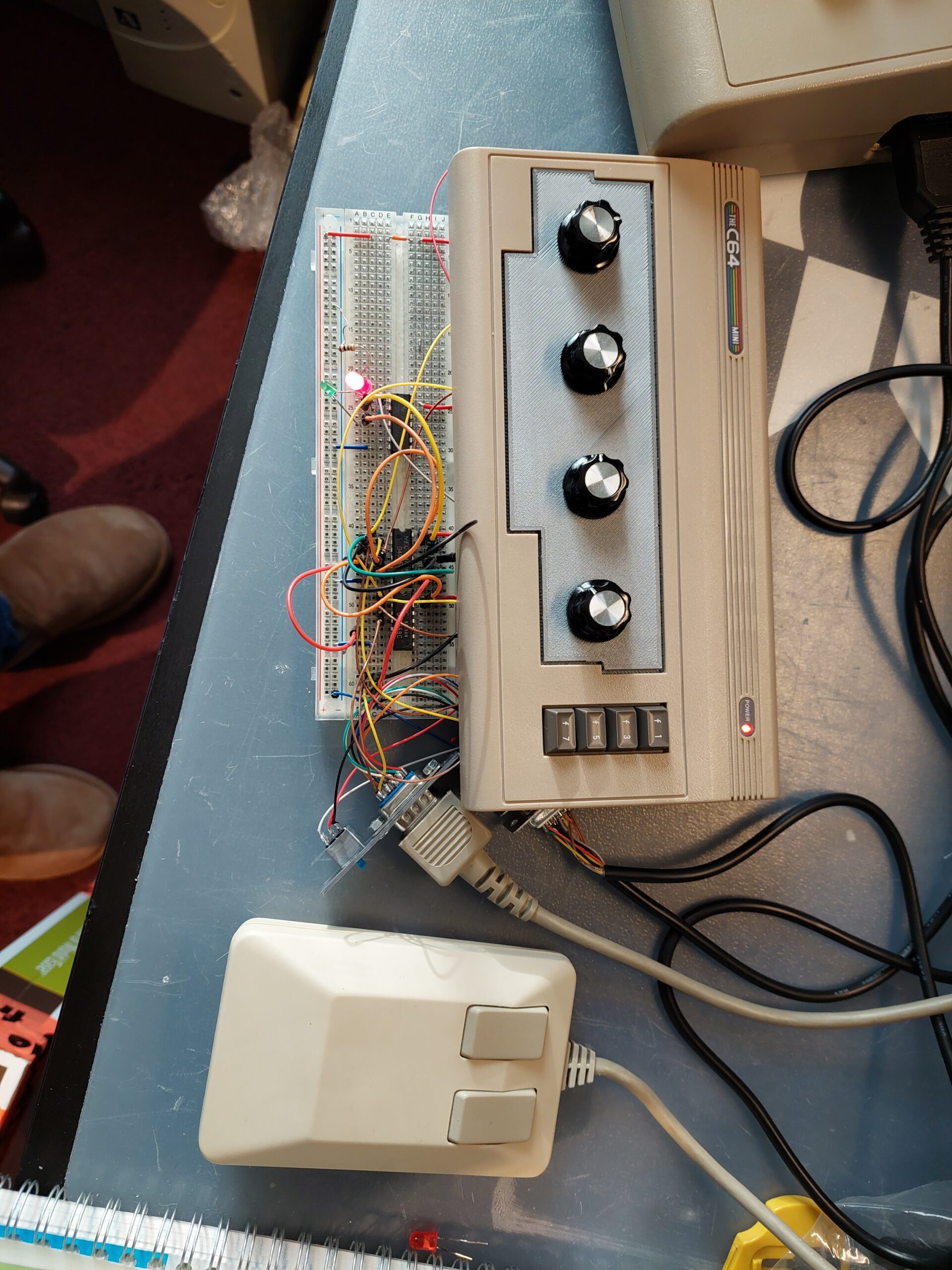
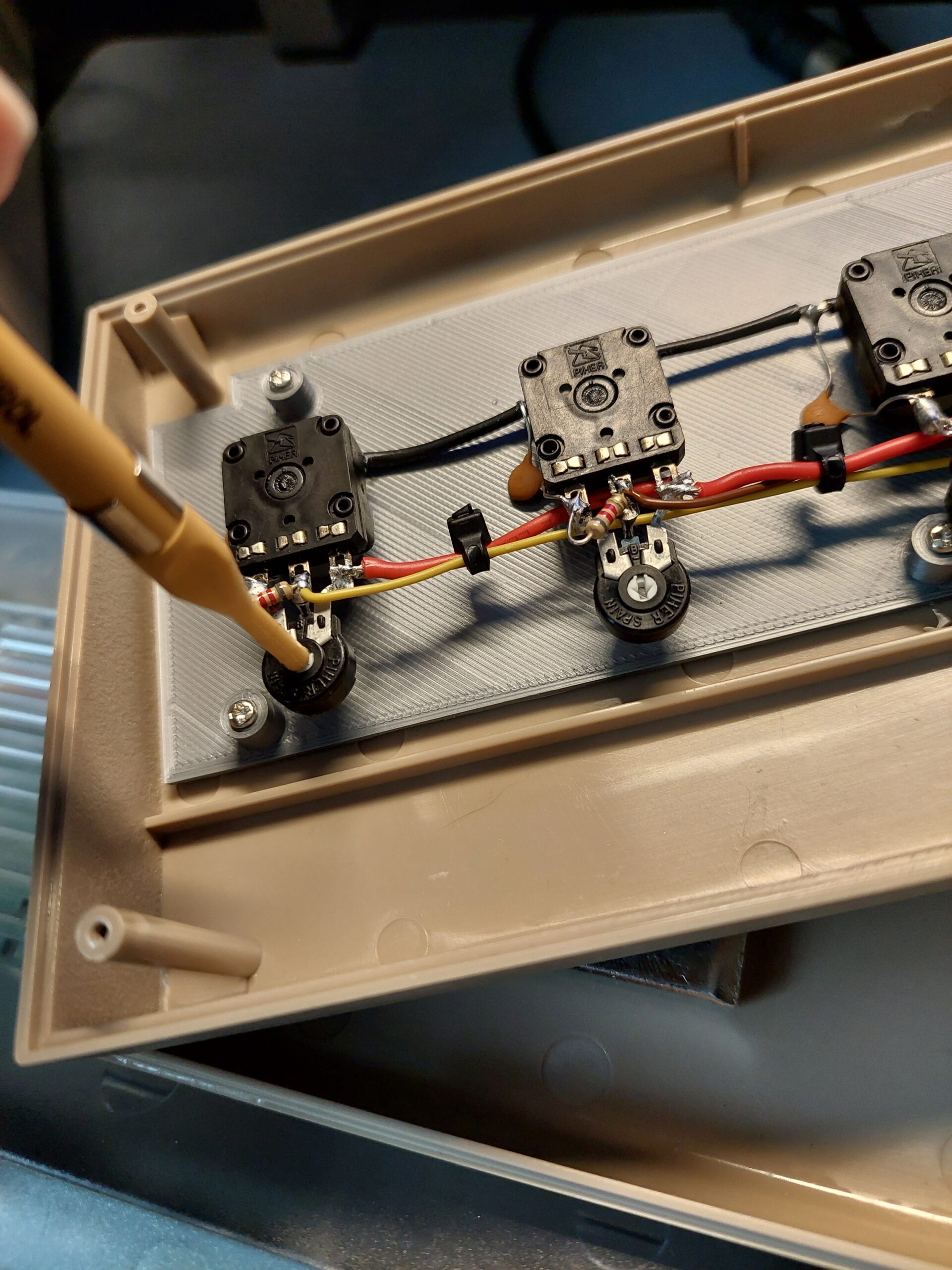
Over here some pictures of building the controller..
Breadboard testing:


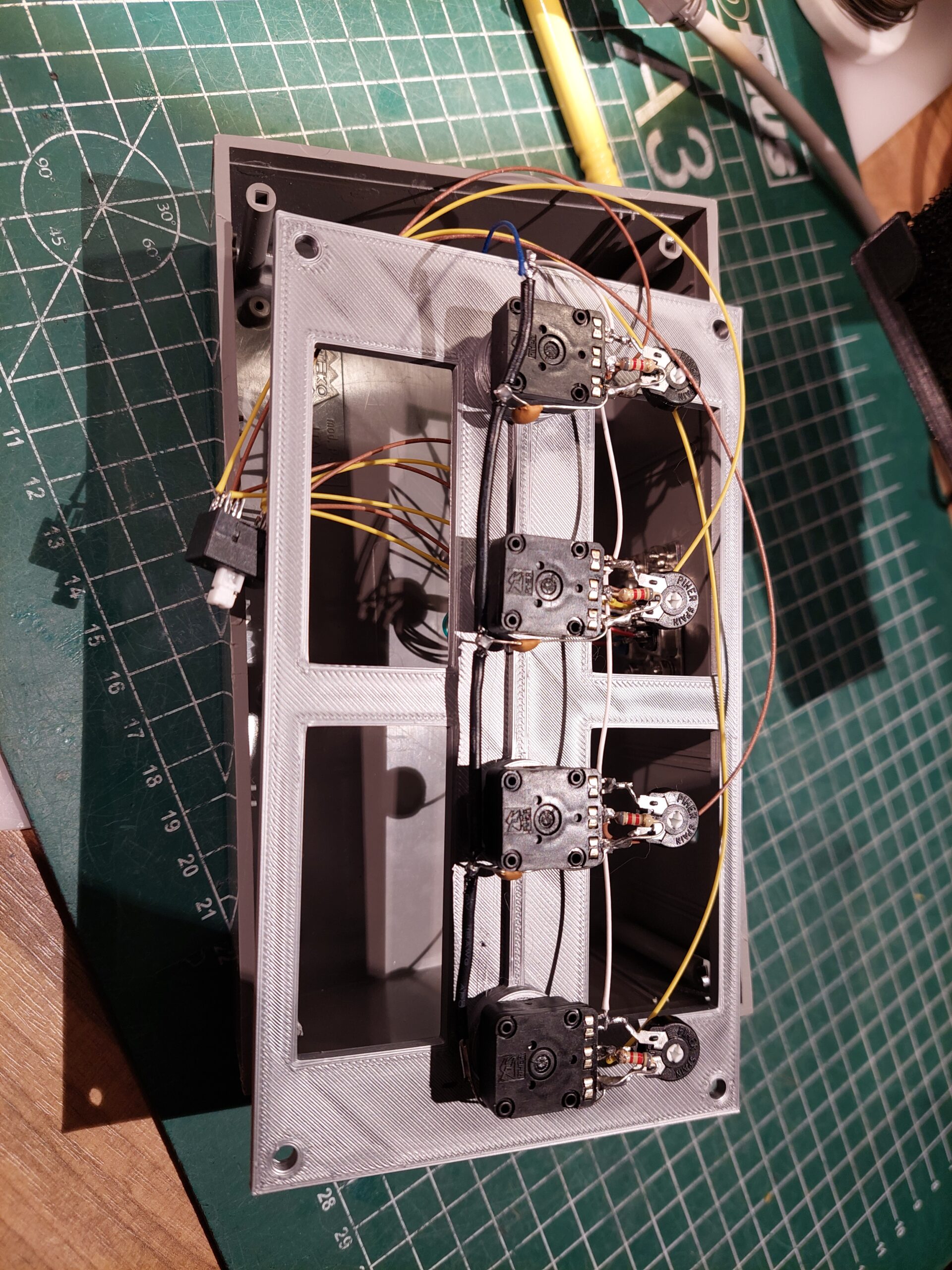
Assembling the controller


Finishing touch


Calibrate pots
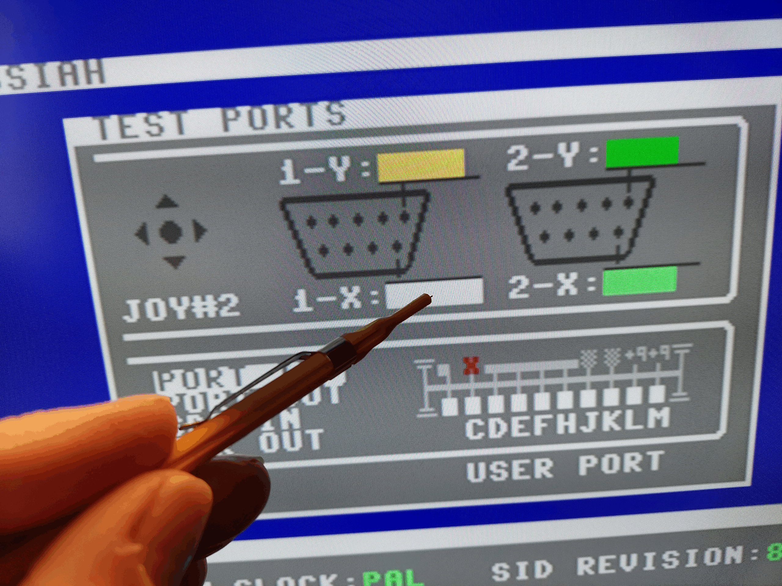
Use the trim pots to calibrate the pots. The MSSIAH Cartridge has a test program for it.
Cable Construction


The connector for the output cable is a D-Sub 15 pin (VGA) connector (see schematic).
I uses the extension cabled to connect the controller box to the C64.
All the signals of the port1 cable are connected to db15 (pin 1..9), on the cable of port 2 only pin 5 & 9 are connected to db15 (pin 10 & 11).
Pinout db15
1 – JOYA0
2 – JOYA1
3 – JOYA2
4 – JOYA3
5 – POT AY (Control port 2)
6 – FIRE
7 – +5V (100mA)
8 – GND
9 – POT AX (Control port 1)
10 – POT BY (Control port 2) ( connect to pin 5 )
11 – POT BX (Control port 2) ( connect to pin 9 )
12 – NC
13 – NC
14 – NC
15 – NC
Custom decal
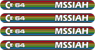
Download the THE C64 mini decal mssiah
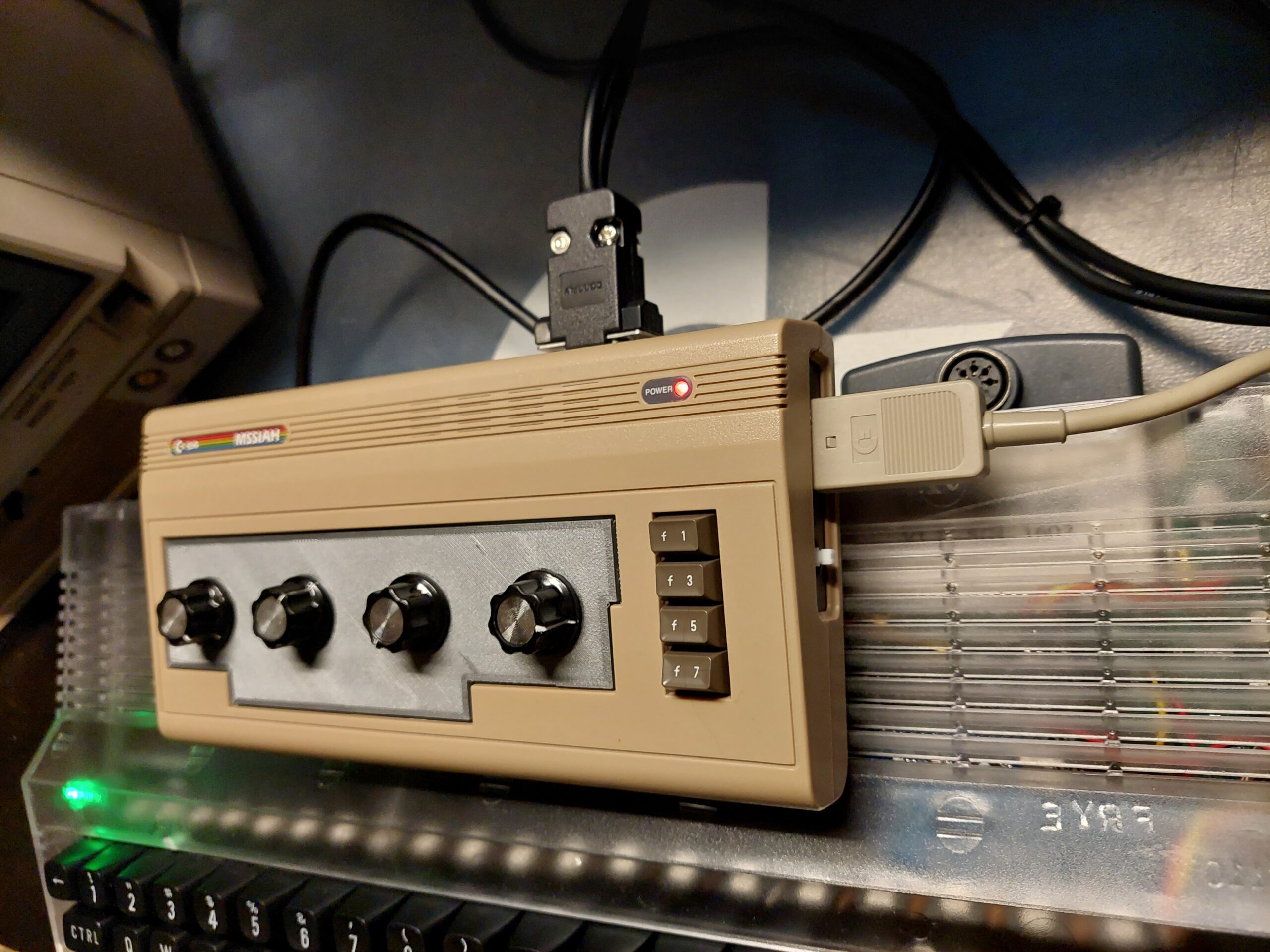
Result
Another custom box
I also made another controller in a different box for a friend of mine.
Made a custom mounting frame for the pots, and put a piece of metal on the bottom on the case, to make it a bit heavier. Designed a top plate decal which I cut out of vinyl with my vinyl-cutter. For this controller I uses the same schematic.