Before we proceed.. THIS IS REAL ROCKET SCIENCE BE CAREFULL! Just kidding!!
You need:
- RGB LED 2*5*7mm with common cathode ( you can find those at your local electronics store )
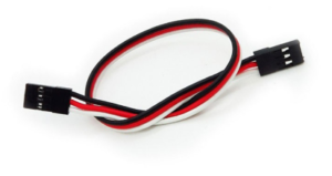
- Header cable with enough length to cover the case width
- Resistors, see table below
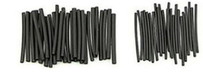
- crimp tubes
The LED


Preview of the colors
Choose the colors that you want to use.
To level the brightness of the colors you need to add some resistors, the resistors I used are:
| Red: | 220R |
| Green: | 2k / 2k2 |
| Blue: | 220R |
You can change the resistor values to your own taste.
The Ultimate64 power led pin output is already driven with a 260KHz PWM ( see wikipedia ) signal.
If there is drive activity the power LED is driven with 2,6V and drive activity LED with 3,2V.
LED pinheader

| Pin | Description |
|---|---|
| 1 | Power |
| 2 | Ground |
| 3 | Drive activity |
read more info about LED pinheader..
Construction
Connect/solder the RGB LED like this:

I would advice you to add the resistor(s) in the middle of the cable, not as i did in my “prototype” direct soldered to the pins of the LED.
Pins of the header connector:
| Pin 1 | Red |
| Pin 2 | Ground |
| Pin 3 | Blue |
I would recommend to add heat crimp tubes over all the solderjoints ( see image below )
Finished cable

Mounted LED in case
Use HEX Inverter to make it switch between colors and not mix the colors on the old U64 firmware boards.
Not NEEDED anymore since release of FW 1.18


Needed components:
- 74HC04 (HEX Inverter)
- 2x Resistor depending on the color you want to use
- 1x RGB LED with common cathode
- Some wires
How it works
The 74hc04 will invert the signal on the incomming pin (1) of the 74hc04, so if the drive activity pin is off (0V) the output on pin 2 of the 74hc04 is 5V.
So the LED connected to the R1 will be on, and the same 5V will be drive pin 3 of the 74hc04, and pin 4 will be off (0V) so the LED on R2 will be off.
So the LED on R1 is the power LED, and the LED on R2 is the drive activity LED.
Power (VCC) can be acquired from the userport.

Userport pinout:
| Pin | Description |
|---|---|
| 1 | Ground (GND) |
| 2 | 5V (VCC) |
Don’t exceed 200mA on the VCC of the userport!!